Introduction
A pre-engineered building is only as reliable as the connections that hold its structural components together. PEB connection design is essential for transferring loads between columns, rafters, purlins, bracing members, and foundations while maintaining the stability of the complete steel structure.
For factory owners, warehouse developers, and industrial investors in Noida, properly designed connections help ensure that the building performs as intended under the loads considered during engineering. Even when individual steel members are adequately designed, unsuitable connections can affect structural performance, complicate erection, and increase maintenance requirements.
At Sumiraj, connection requirements are an important consideration in planning pre-engineered buildings for industrial applications. From bolted beam-to-column joints to column base plates and bracing connections, each detail must be coordinated with the structural design, fabrication drawings, and site installation requirements.
What Is PEB Connection Design?
PEB connection design is the engineering process of determining how structural members are joined and how forces pass between them.
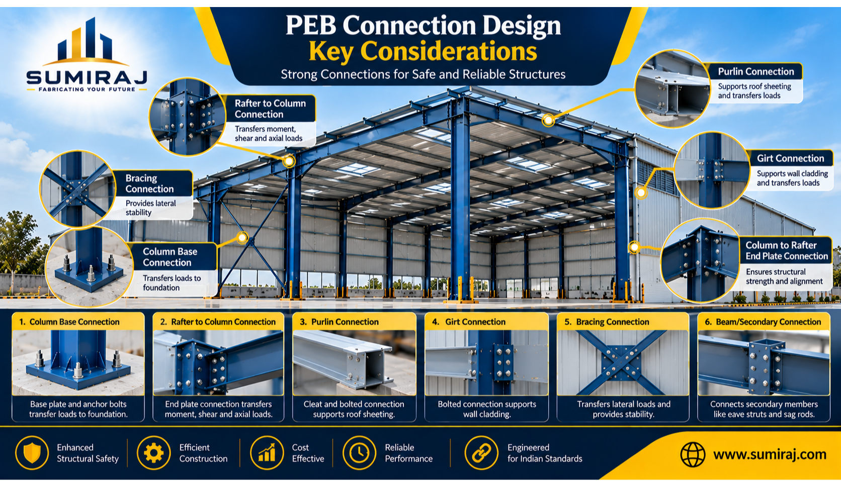
A typical pre-engineered building includes several types of connections. These may use high-strength bolts, welds, plates, cleats, stiffeners, and anchor bolts, depending on the structural arrangement and design requirements.
Connections must perform their intended structural function without creating unacceptable weaknesses or excessive deformation. Their design considers the forces acting on the joint, the geometry of the connected members, material properties, fabrication tolerances, and erection conditions.
For example, a rigid connection between a column and rafter may be designed to transfer bending moment, shear, and axial force. A bracing connection may primarily transfer tension or compression, depending on the bracing system and design assumptions.
Understanding these differences is important because not all PEB connections perform the same function.
1. Load Transfer and Structural Requirements
The first consideration in PEB connection design is understanding the forces that each connection must transfer.
These forces are determined through structural analysis and depend on the building's geometry, loading conditions, and structural system.
Dead Loads and Roof Loads
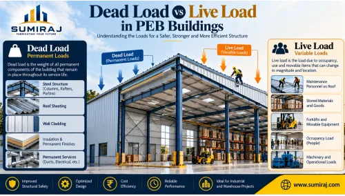
Dead loads include the self-weight of the structural frame, roof sheeting, cladding, and permanently installed components. Connections must transfer the relevant loads through the structural system towards the foundations.
Additional roof loads, including maintenance loads and other specified imposed loads, must also be considered where applicable.
Wind Loads
Wind can create pressure and suction on the roof and walls. These forces must be transferred through the cladding supports, secondary framing, primary structure, bracing system, and foundations.
Connections between purlins and rafters, girts and columns, and bracing members and their supports must therefore be designed according to their assigned structural functions.
Crane and Equipment Loads
Some manufacturing facilities require overhead cranes, suspended equipment, or specialized machinery. These may introduce additional forces, including horizontal effects, vibration, and concentrated loads.
Where such equipment is planned, its loads and connection requirements must be included in the engineering design. A standard connection detail should not automatically be assumed suitable for a specialised application.
2. Bolted Connections in PEB Structures
Bolted connections are widely used in pre-engineered buildings because they can support efficient site assembly and allow components to be joined according to approved drawings.
Typical applications include column-to-rafter joints, purlin connections, bracing joints, and other structural interfaces.
Bolt Grade and Diameter
Bolt grade and diameter must be selected according to the design forces, connected plate thicknesses, and applicable requirements.
Using a bolt of the wrong grade or diameter can affect the capacity of the connection. The number and arrangement of bolts must also be determined through engineering calculations.
Bolt Spacing and Edge Distance
Bolt spacing and edge distance affect the connection's resistance to different failure modes. These dimensions must follow the approved design and applicable detailing requirements.
Insufficient edge distance, poorly positioned holes, or incorrect bolt arrangements may lead to problems during assembly or reduce the intended connection capacity.
Installation and Tightening
Bolts must be installed using the specified procedures. Where pretensioned or slip-resistant connections are required, the applicable installation and inspection requirements must be followed.
The installation team should verify that the correct fasteners are used and that the completed connection matches the approved drawings.
3. Welded Connections and Their Importance
Welded connections join steel components by creating a continuous or specified local connection between them. They are commonly used in fabrication shops to assemble built-up sections, stiffeners, plates, and other structural details.
Weld Type and Size
The required weld type, length, size, and location depend on the forces being transferred and the joint configuration.
Fillet welds may be suitable for certain joints, while other configurations may require different weld arrangements. The selected detail must meet the relevant structural and fabrication requirements.
Welding Procedures
Welding should be carried out according to the specified procedure, with suitable materials and qualified personnel where required.
Important controls may include joint preparation, welding parameters, consumable selection, and management of distortion.
Weld Inspection
Visual inspection helps identify surface defects such as visible cracks, undercut, and unacceptable weld profiles. Additional non-destructive testing may be required for specified joints or projects.
The inspection method and acceptance criteria should be established in the project quality requirements rather than applied inconsistently.
4. Column Base Plate and Foundation Connections
Column base connections transfer forces from the steel frame into the foundation system. They commonly include a base plate, anchor bolts, and other details specified by the design.
These connections must be coordinated with the concrete foundation and the anchor-bolt layout.
Base Plate Design
The base plate distributes the forces transferred by the column to the supporting concrete. Its dimensions and thickness depend on the design forces, column configuration, bearing conditions, and connection arrangement.
Where required, stiffeners may be included to improve the behavior of the base connection.
Anchor Bolt Placement
Anchor bolts connect the steel base plate to the foundation system. Their diameter, grade, embedment, spacing, and arrangement must match the approved design.
Incorrect anchor-bolt positioning can make column installation difficult and may require engineering assessment before corrective work is undertaken.
Foundation Coordination
The structural engineer and civil contractor should coordinate the base-plate details with the foundation drawings.
Concrete strength, foundation dimensions, reinforcement, anchor-bolt installation, and any specified grouting arrangements must be considered as part of the overall connection system.
5. Bracing Connections and Structural Stability
Bracing systems help transfer lateral forces through designated structural load paths. Their connections are therefore important to the stability of the building.
Common bracing arrangements include roof-plane bracing and vertical wall bracing. Depending on the design, bracing members may connect through gusset plates, cleats, bolts, or other specified details.
The connection must transfer the required forces without compromising the intended behavior of the bracing system.
For example, a tension-bracing connection must be capable of transferring the design tensile force. If the system also relies on members resisting compression, their behaviour and connection requirements must be evaluated accordingly.
Bracing locations should also be coordinated with industrial doors, loading areas, and other openings. Any proposed alteration to a bracing member or connection requires review by the responsible structural engineer.
6. Connection Design for Purlins and Girts
Purlins support roof cladding, while girts support wall cladding. Their connections transfer the relevant loads to the primary structural frame.
Although these connections may be smaller than major frame joints, they remain important to the building's performance.
Purlin Connections
Purlin connections must accommodate the specified loads and work with the selected purlin arrangement. Depending on the design, details may include cleats, bolts, and provisions for member continuity or restraint.
The connection must also be coordinated with roof geometry, cladding installation, and any required restraint systems.
Girt Connections
Girt connections transfer wall-related loads to the columns or other designated supports. Their design must consider wall cladding, wind pressure and suction, opening arrangements, and the supporting member configuration.
Accurate connection detailing helps reduce alignment problems during erection and supports proper installation of the building envelope.
7. Fabrication Accuracy and Erection Tolerances
A structurally sound connection must also be practical to fabricate and assemble.
Fabrication drawings should clearly identify connection plate dimensions, bolt-hole locations, weld details, member orientation, and other information required by the production team.
Dimensional checks during fabrication help confirm that the components match the approved drawings. Poor alignment or misplaced holes can lead to delays and may encourage unsafe site modifications if not addressed correctly.
During erection, the contractor should verify member positioning, connection alignment, and the specified fastening or welding procedures.
Site adjustments that change a connection's geometry or structural behaviour should not be made without appropriate engineering approval.
Benefits of Proper PEB Connection Design
A well-engineered connection system provides several practical benefits for industrial building projects.
1. Reliable Load Transfer
Connections designed for their intended forces help the structural frame behave according to the engineering assumptions.
2. Improved Structural Stability
Correctly detailed joints support the performance of the primary frame, secondary members, and bracing system under the specified design conditions.
3. Efficient Fabrication and Erection
Clear drawings and accurate fabrication reduce avoidable site adjustments and help installation teams assemble components in the correct sequence.
4. Better Quality Control
Defined connection details make it easier to inspect bolts, welds, plate dimensions, and other important requirements.
5. Maintenance and Serviceability
Suitable materials, protective coatings, and accessible connection details can support inspection and maintenance throughout the building's service life.
6. Better Project Coordination
Early coordination between structural engineers, fabricators, civil contractors, and erection teams helps identify interface issues before they affect site progress.
Applications of PEB Connection Design
Connection design is important across a wide range of steel-framed industrial facilities, including:
Manufacturing plants: Connections for primary frames, equipment-supporting structures, and specialized loading requirements.
Warehouses: Joints supporting roof frames, wall systems, and large clear-span structures.
Logistics centers: Connections coordinated with loading docks, access openings, and operational layouts.
Industrial sheds: Structural joints for fabrication workshops, storage buildings, and service facilities.
Automotive facilities: Connections designed around the building's operational and equipment requirements.
Crane-equipped buildings: Specialized connections designed for applicable crane and supporting-structure loads.
The connection arrangement must reflect each building's structural system and operational needs.
PEB Connection Design for Projects in Noida
Industrial businesses in Noida need connection details that suit their building dimensions, loading requirements, site conditions, and construction methods.
Before fabrication begins, project teams should confirm the approved structural drawings, connection calculations where required, bolt and weld specifications, base-plate details, and inspection criteria.
Coordination between the PEB manufacturer, structural engineer, civil contractor, and erection team is especially important for anchor bolts and foundation interfaces.
Projects involving overhead cranes, specialized machinery, or unusual loading conditions require these factors to be incorporated into the design from the beginning.
Applicable Indian standards and project-specific requirements should guide structural analysis, connection detailing, fabrication, and inspection.
Why Choose Sumiraj for PEB Connection Design?
Sumiraj recognizes that dependable steel buildings require coordinated engineering, fabrication, and installation planning.
Key considerations include:
Engineering expertise: Coordinating connection requirements with the primary frame, secondary members, bracing, and foundations.
Quality steel: Using materials and components according to approved project specifications.
Customized designs: Accounting for building dimensions, structural loads, and operational requirements.
Cost efficiency: Evaluating connection details to support appropriate material use and practical fabrication.
Timely delivery: Supporting project schedules through coordinated drawings and fabrication requirements.
Indian standards: Considering applicable Indian standards and project-specific engineering requirements.
Technical support: Helping clients understand connection specifications and their role in the building system.
A coordinated approach helps industrial buyers review connection requirements before fabrication and erection begin.
Frequently Asked Questions
1. What is PEB connection design?
PEB connection design determines how structural members are joined and how forces transfer between columns, rafters, purlins, girts, bracing members, and foundations.
2. Which connections are commonly used in PEB structures?
Common connections include bolted frame joints, welded fabrication joints, column base connections, bracing connections, and purlin or girt connections. The appropriate type depends on the structural design.
3. Are bolted connections better than welded connections?
Neither is universally better. Bolted and welded connections serve different purposes. The selection depends on structural forces, fabrication requirements, erection methods, inspection needs, and project specifications.
4. Why are column base plates important?
Base plates help transfer forces from steel columns to the supporting foundation. Their dimensions and anchor-bolt arrangements must be designed for the relevant forces and coordinated with the civil works.
5. What happens if a PEB connection is incorrectly fabricated?
Incorrect hole positions, plate dimensions, weld details, or fasteners can create assembly difficulties and may affect structural performance. The issue should be assessed and corrected through an approved engineering process.
6. Which standards apply to PEB connection design in India?
The applicable standards depend on the structural system, materials, loads, and project specifications. Relevant Indian standards should be identified by the responsible structural engineer for the specific project.
7. Can connection details be changed at the construction site?
Structural connection details should not be changed without appropriate engineering review and approval. Unauthorised modifications can affect the intended load-transfer mechanism and structural safety.
Conclusion
PEB connection design is a fundamental part of creating a safe and reliable pre-engineered building. Bolted joints, welded connections, base plates, bracing joints, and secondary-member connections must all be designed and coordinated according to their structural functions.
For factory owners, warehouse developers, and industrial investors in Noida, careful attention to connection design helps support structural performance, fabrication accuracy, and efficient site erection. Approved drawings, suitable materials, controlled fabrication, and appropriate inspection are essential to achieving the intended results.
Sumiraj can help industrial buyers evaluate their PEB requirements and coordinate structural components according to project-specific engineering and fabrication needs.
Discuss Your Project With Sumiraj
Planning a factory, warehouse, or industrial shed? Contact Sumiraj via WhatsApp or phone to discuss your project dimensions, structural requirements, connection details, and PEB specifications.
Subscribe to our updates and stay informed about the latest trends, innovations, and cost-saving solutions in PEB construction, industrial buildings, and warehouse development.